|
|
|
|
|
|
|
FEATURES
HARDWAREAutoExplorer 1 hardware consists of the following components:
OBDxplorer SOFTWARE DEMONSTRATIONInitial Display PanelThe initial display of the program is presented in Picture 1. A detailed description of the various functions of the program follows. |
|
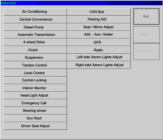
Picture 2: Communication with other subsystems.
The user can read sensor input/output data, as illustrated in Picture 3.
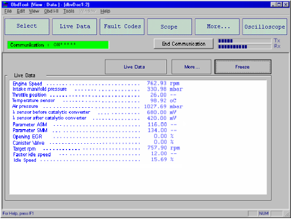
Picture 3: Live Data.
Output signals or parameter values is continuously renewed, and the user is able to "freeze" the data, by clicking the Freeze Data button (for example to see the data when a problem occurs to the vehicle). By clicking the "Live Data" button, data transmission starts again. If a vehicle provides more data than those that can be accommodated on the display panel, then by clicking the More button, the user can see data provided by more sensors or parameters.
By clicking the Fault Codes button, the user is able to read and erase fault codes stored in the ECU (Picture 4). The fault codes can be read just by clicking the Read... button. The text that appears describes in detail the component (e.g. throttle position sensor), the symptom (open or short circuit, etc.), provided that the vehicle ECU supports this functionality. After the malfunction has been repaired, the stored fault codes can be erased, by clicking the Erase... button. As a result, the Check Engine light on the instrument panel of the vehicle will also turn off.
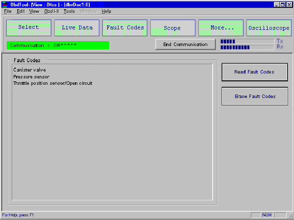
Picture 4: Fault codes.
By clicking the Scope button, a new display panel appears, showing an oscilloscope screen where live data is plotted against time. The user is able to select the sensors to be monitored. Signals appear in different colors and are also described in text at the top left corner of the screen. There is no limitation concerning the number of the signals that can be monitored at the same time, however it is suggested not to select more than five signals simultaneously, so as not to slow down the processing.
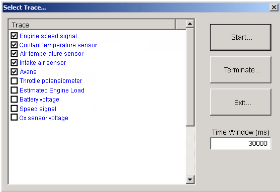
Picture 5: Selecting signals for scope analysis.
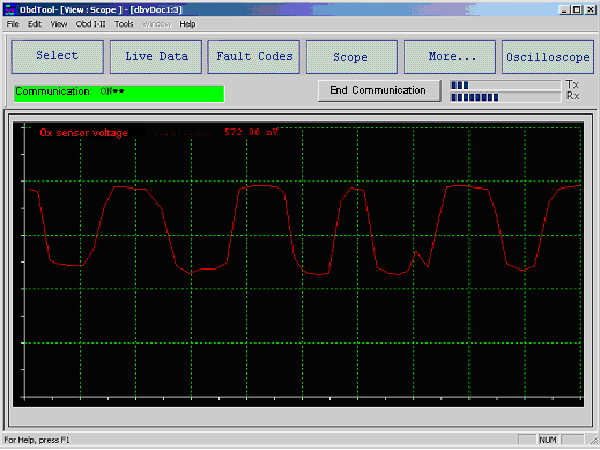
Picture 6: Scope.
The graphical analysis of the signals is very helpful, since the user can see and analyze many sensors at the same time, so as to detect a problem of the vehicle even when it has not been stored as a fault code.
By clicking the More button, the user is able to make component activation, as well as basic setting procedures on certain vehicles, just by selecting the desired option. The activation of a component helps the user to find out if the selected component operates correctly, despite the vehicle's operation parameters. Typical components that can be activated are injectors, charcoal canister purge valve, idle speed control servo/stepper motors, etc. Depending on vehicle's software, there are two activation processes. Moreover, by selecting the Status option, the user is able to view the signal that the ECU receives or transmits to some components or systems (Picture 8). For example, the user can read throttle status (idle, partial load, full load, etc.), fuel mixture control (open/closed loop), fuel vapor control system status etc.
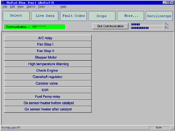
Picture 7: More...: Activations in group Fiat and Peugeot, Renault, Citroen vehicles.
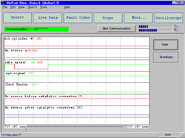
Picture 8: More...: ON/OFF statuses.
An example of Basic Settings is the 5-digit immobilizer key coderecording in many group VAG vehicles (Picture 9).
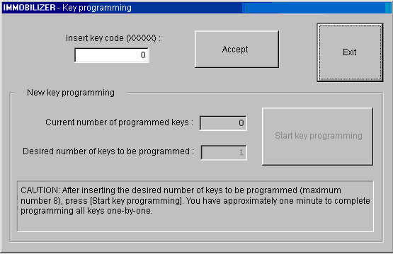
Picture 9: More...: Basic Settings (5-digit immobilizer key code recording example).
By selecting Service Reset, we can reset all service or oil indications in many group VAG vehicles (Picture 10).
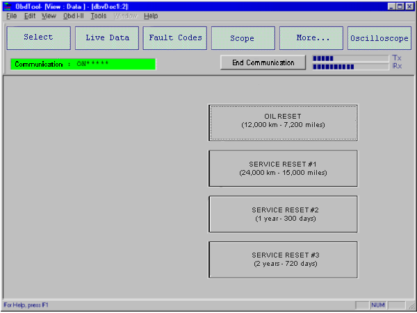
Picture 10: More...: Service Reset.
By clicking Oscilloscope on the top right corner of the screen, a new window appears (Picture 11), which provides you with an external oscilloscope tool.
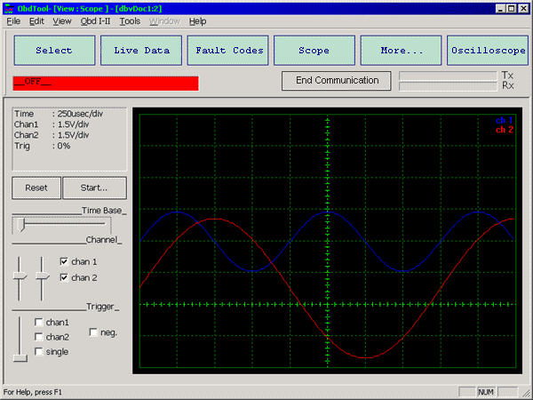
Picture 11: Oscilloscope.
Notice: The original displays of the product may be slightly different from the ones presented in this demonstration.
AutoExplorer 1 is a product, which was designed with the most recent technology and has the most compact design ever built! It is simple, user-friendly and comes with a complete technical support by our expert technical support team.
AutoExplorer 1 is based on a very powerfull platform (both hardware and software), so as to cover the need for diagnostic systems not only today, but in the future as well.
AutoExplorer 1 covers serial communication with an extreme variety of vehicles, including E-OBD communication. In many cases, apart from reading/erasing fault codes in engine management, it is also possible to make activations and basic settings, monitor the sensor signals graphically and communicate with other systems, such as ABS, SRS, etc.
|
|
What does each package include?AutoExplorer 1 is offered in a handy high-resistant plastic case, which includes, apart from hardware, 1 CD-ROM with the software and 1 User Manual. |
Features Hardware Software Demonstation Requirements |
To be able to use our products, you must have a PC with the following specifications:
Minimum System Requirements
| Processor: | Pentium® I, 233 MHz or equivalent |
| Operating System: | Microsoft® Windows® 98 Second Edition |
| RAM: | 32 MB |
| Hard Disk: | 200 MB free disk space |
| Extra: | 1 serial port or if not present, USB port for PC connection with USB cable |
Recommended Configuration
Operating
System:
Microsoft®
Windows® 2000
or XP
Processor:
Pentium® III,
650 MHz or better processor
RAM:
128 MB or higher
CAUTION: The use of the application with Microsoft® Windows® ME operating system is not recommended.
AutoExplorer 1 consists of two programs: OBDxplorer and EOBD. Both programs have user-friendly interface, so that they are easy to use, even for users with limited PC knowledge.
OBDxplorer is used for engine checking, as well as ABS, SRS, etc. and it uses the communication protocols that are suggested by the manufacturer and not the European Union. Thus, it is suitable for vehicles with manufacture year 1988 and later (european - corean - japanese).
| BASIC FUNCTIONS | SPECIAL FUNCTIONS |
| Read / Erase trouble codes | ECU recognition |
| Live Data display | Immobilizer key programming |
| Oscilloscope | Reset Service/Oil intervals |
| Component activations | AVANS fine trimming |
| Basic Settings | CAN bus diagnosis |
| System Status view |
You can find more information about OBDxplorer software in the Demonstration.
EOBD software is suitable only for vehicles with manufacture year 2001 or later and it checks only engine and gas emission problems. EOBD communicates with all european protocols and covers all european, japanese and korean models.
| FUNCTIONS |
| Read / Erase engine trouble codes |
| Read all stored and pending DTC's |
| Live Data display |
| Freeze Frame Data display |
| Oscilloscope |
| Printing test results |
You can find more information about EOBD software in the Demonstration.
|
Send mail to Kalatzisport@hotmail.com with
questions or comments about this web site.
|